I am using two different elements to control my layout: a touchscreen command station (the excellent ESU ECOS II), and a PC software (Freiwald’s TrainController Gold). I wanted to switch from S88 train detection to a Loconet network, far more flexible.
The ECOS is not Loconet compatible and I had no intention of buying another control center, so I had to create a “standalone” Loconet network, and connect it directly to my PC. Here is how I did that, for less than 100€.
Standalone Loconet limitations
I wanted the benefits of Loconet (train detection, accessory control) without spending big money on a Loconet enabled command station:

Normal vs. standalone Loconet
This looks simple, but before reading further, please be aware of the limitations of a standalone Loconet:
- PC Only
Feedback (or Loconet commands) can only be sent to and from a computer, with a compatible piece of software. The following will NOT render your ESU ECOS (or Märklin Central Station) Loconet compatible.
Also, you will not be able to control any train: your Loconet network will be limited to occupancy detection and accessory control. - Programming of new modules a bit more difficult
Uhlenbrock (a German manufacturer using Loconet) and Digitrax (the Loconet creator) have rendered it quite easy to program their modules with their command stations. With a standalone Loconet, you will still be able to configure the Loconet parameters of Uhlenbrock or Digitrax modules, but it may be a bit more tricky. - Soldering needed
You will need basic soldering skills to create the power supply for the loconet. You also need to have some basic idea of what a transistor is (and how to mix its 3 “poles”).
You don’t need to be an expert (I am not!), but some DIY is in order
A standalone loconet only responds to certain needs. If you don’t have a Command Station yet and wish to have a Loconet network, I advise buying directly a Loconet enabled command station.
Principle
A Loconet is a very basic network. It needs 2 things, that are usually integrated in a command station:
- A 500mA power supply, 12V being a good voltage (compatible with all modules on the market).
- A “terminator” that will correctly inject this power on the appropriate wires.
Additionally, for a standalone Loconet, you’ll want to connect it to a PC. The best option I have come around is the Locobuffer-USB from RR-Circuits.

Locobuffer USB from RR-Circuits,
to connect the Loconet to a PC
Important note on the terminator function of the Locobuffer:
The locobuffer has a (jumper) setting, that makes it a terminator for the Loconet. However (as stated by RR-Circuits), using this option puts your computer at risk: with this setting, the USB and Loconet are not optically isolated anymore. This would mean potentially exposing your PC to surges from your model railroad.
Since this was not an option, and thanks to many users feedback on the German forum “1zu160.net”, I found another solution.
What we are going to do:
- Build a DIY device that will provide the 2 functions we need (power supply and termination)
- Keep the Locobuffer USB to its default setting: being a simple interface between USB and Loconet.
But first, here is a short overview of how the Loconet plug, and what the 6 wires do:

Pin 1 – Pin 6 : Railsync (+)
Pin 2 – Pin 5 : Ground (-)
Pin 3 – Pin 4 : Loconet data
As you can see, the loconet plug is symmetric. And now we understand better what the terminator does: it pumps power from the Railsync pins, and injects it (according to Loconet standard) to the data pins, allowing devices to communicate. This is why just “powering” the Loconet (on Pins 1/6-2/5) is not sufficient.
Make sure you understand this simple list before building your own terminator.
Hardware and assembly
1) Power supply
Power will be provided by a simple power adapter. This can be bought in any electronics store (eg. Conrad in Germany, or Radioshack in the US). This adapter must be 12V, 500mA, not more !

2) Building the “Terminator”
The terminator is the tricky part. You will need to build a small electronic circuit. It’s pretty basic really, 2 transistors, 2 diodes, an elko and 2 resistors.
The circuit is provided by Reinhard Müller and the schematics are here: http://www.dcc-mueller.de/loconet/lnpull_e.htm
One thing to note is that this circuit is not actually “made” for a standalone Loconet: it is made as a “backup terminator” for super large Loconet network. But it will do exactly what we do: provide the termination.
Make sure you understand the schematic, get the right parts (see bottom of this blog post), and you’re ready for some DIY:
- Recreate the schematics from Mr. Müller.
I used a striped electronic test plate, and simply soldered some wires between the different components:

Test plate, that we will use as a base for our DIY operation
- Now, bear with me, there is one thing that the Müller schematics don’t include: the power supply.
So in addition to the schematics above, we will do the following: connect the + of our power supply to pins 1 and 6, and the – to pins 2 and 5. I advise adding an extra Diode coming from the + of the power supply, to pins 1 and 6. This is an extra protection that was advised by people on the forums I read.
And that’s it! Now, it will take you some time to bring the components together, and I can’t help you for that.
But we are missing a part aren’t we? Where are our loconet plugs? Well the Müller schematics is a “dead end”, it only shows on Loconet ending. The good news is, building a “HUB” for Loconet is a bliss: you can’t connect as manny RJ12 plugs as you want, in a 1:1 fashion (all pins 1 together, all pins 2 together…). That’s it, so let’s do it:
- Add RJ12 connectors to your montage, as many as you want, but I advise at least 2. One that will go the Locobuffer USB, and the other for your Loconet devices.
For my part, I added a third RJ12 plug in, so I can plug new modules for easy configuration next to my computer.
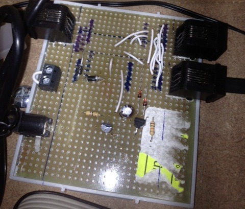
The result: it’s ugly, it’s unprofessional. But it took an hour and works perfectly!
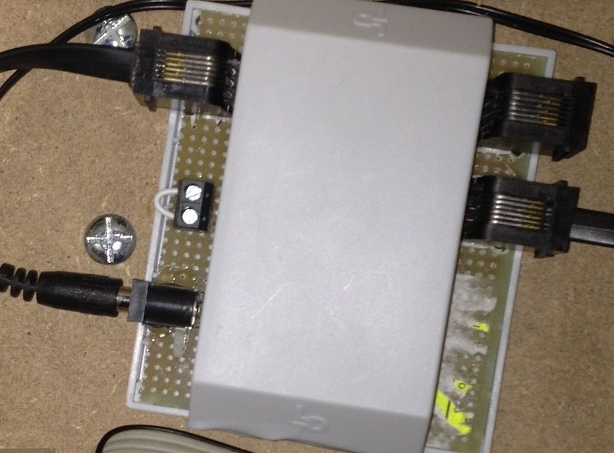
On the final picture above, you can clearly see the different elements:
- The Müller schematics (transistors…), simply soldered with wires on the test plate
- The 12V Plug for the power supply
- 3 Loconet plugs (1 for the Locobuffer USB, 1 to all my devices, and 1 for testing modules)
Testing the result
Now, I am not an electronic expert. Frankly I didn’t even try to figure out exactly what this montage does 😉 . But there are a few common sense tests that you can do before pluging expensive Loconet devices to your Power+Terminator device:
- Plug the 12V power supply it, if it doesn’t explode, that’s a good sign!
Use a Voltmeter to to test the following:
- 12V between pins 1 and 2, and between 4 and 5 respectively
- Some voltage between pins 3 and 2, and 4 and 5 respectively
Make sure it is symmetric! The readings you should get for one side should be the same on the other.
If everything goes well, you just built yourself a power supply AND terminator to create a standalone Loconet network; therefore sparing about 300-500€ in a new command station, for only about 20€ of components. The next steps include of course connecting the Locobuffer USB and Loconet devices, but this is another story….

The final result, connected to the Locobuffer USB
As always, this article is just the sum of tips that I got from different places. I tried to gather it all in one place, and hope this will be helpful!
Update 07/2013 for those who don’t want to solder!
I just discovered this. A german manufacturer, Bluecher Elektronik, sells a module that does exactly what my DIY module does: it provides Loconet with a termination, and power is with a 12V external power supply. The product page is here and the instruction PDF is here (in German, use Google Translate).
Setting this module as a terminator for a standalone Loconet (without Loconet Command station) implies just changing one jumper on the board. One should note, that they advise the exact same thing as I do: this extra board needs to be the terminator, not the Locobuffer. The termination function of the Locobuffer USB should not be used, as it cancels the short circuit protection between Loconet and USB (computer).
External links
- Explanation of the Loconet Pins: http://www.railwaybob.com/Modules/WiringRJ12s/RJ12s01.html
- Loconet “termination” schematics: http://www.dcc-mueller.de/loconet/lnpull_e.htm
- Standalone Loconet Page from the JMRI project: http://jmri.sourceforge.net/help/en/html/hardware/loconet/StandaloneLocoNet.shtml
- Loconet page at Digitrax, the inventor of Loconet: http://ikm.digitrax.com/questions.php?questionid=1484
Part list
(references are for “Conrad” stores in Germany, but all parts are very easy to find wherever you are)
- ref. 514223 / 12V 500mA power source
- ref. 738882 / power supply connector (matching the power adapter plug)
- ref. 530809 / test plate for mounting our DIY device
- ref. 716136 / RJ12 connectors
- The other components (transistor, resistors…) are easy to buy.
If you are like me, and don’t know anything about them: go to an electronic components store and show them the Müller schematics, they’ll give you what you need!


Do you have any experience with the Digitrax PR3 unit as a stand-alone Loconet unit?
Hi, I don’t.
As far as I remember though, this PR3 is supposed to be used as a PC interface in combination with a Loconet control station. That means it probably doesn’t provide the termination or the power to the Loconet.I think you could use this PR3 for a standalone Loconet, but you’d still need to build a loconet termination and power supply. This would be the same setup as mine, as described in this post, just with a different PC interface device. The Locobuffer USB was described as the best choice when I did my research; I don’t remember if the PR3 had limitations or why I didn’t go for it, maybe simply because it was harder to find for me in Europe.
Pierre, consider Raspberry Pi credit card sized PC as standalone control centre. Google Raspberry Pi
Thanks Jimmy. In fact, I already have 3 Raspberry Pis. 1 is for Home Automation, 1 is a Personal Cloud…I love them, I’m not just a train geek!
But for train control in my case? Over my dead body 😉
I spent €1000+ on the ESU Ecos II (one of the best command stations IMHO), and Train Controller Gold (one of the best train automation software IMHO).
I don’t want to play for weeks with a Raspi, and obtain 10% of what I can achieve in an hour with what I already have!
That said, this is a very good tip. I have seen people playing with Raspi and trains, I am sure it can be fun as well!
It probably wasn’t available when you wrote this, but ESU now has a LocoNet to ECoSlink converter, no. 50097
http://www.esu.eu/en/products/digital-control/lnet-converter/
Thanks! In fact, I think I had already heard about the L.net converter back then (it has been announced for a long long time, and just arrived before summer).
As expected though: no PC software is able to access the Loconet detection information through the ECOS. This might change soon though.